
Connecting a GPS (EB-85) to a PIC microcontroller
Last month I finally bought a GPS module. I decided on the EB-85 because it’s cheap (thanks to mr. rc-cam!) and it has a 5Hz update rate!
However, this module has an UART that operates at 2.8V. My PIC runs at 5V. After some investigations I figures out that the TTL pins of my PIC would interprete the 2.8V as logical high, but the ST-pins (Schmitt-trigger) won’t. Because the hardware UART or PIC uses ST, I was left with 2 options: Use the TTL-pins and a software UART or continue looking for another solution :-)
What I need is a TTL chip that has en open-collector output. TTL accepts 2.8V as a logical high, and the open-collector port allows me to use any voltage as logical out if I use a pull-up resistor.
My solution uses the 7407 IC, which is a “Hex Buffers/Drivers With Open-Collector High-Voltage Outputs”.
This is the schematic:
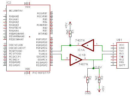
On the left you see the PIC, on the right you see the connector to my GPS. In the center-top you see the pull-up resistor to 5V, in the center-bottom you see the pull-up resistor to 2.8V that consists of a voltage divider that yields 2.8V.
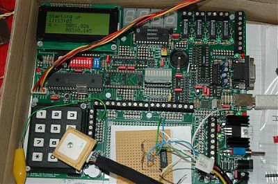
On my test-board it looks as follows:
This is what my test-program does:
- Startup
- Send a message to the GPS so only the RMC (Recommanded minimum) messages come through:
- Every time a byte is received on the UART, an interrupt is launched and the received data is decoded.
- The main loop prints the data in the LCD
The overhead of the UART and GPS decoding is very low on my 4Mhz PIC. Perfect!
Here are some nice sites for electronics newbies like myself:
Update:
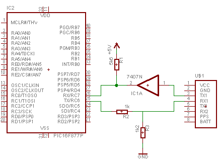
There was a slight error in my schematic: I played the voltage divider before the buffer instead of after it. It is corrected now.
This should also work (but my 7407 chip has 6 buffers so I didn’t care):
|